Wrong alignment tool for the situation or asset? Need a more experienced user to get the job done? Many complexities can arise when attempting to diagnose and correct machinery misalignment with laser shaft alignment solutions not built for the challenge.
In an August 2020 webinar, Jonathan Gough, PRUFTECHNIK Product Manager at Fluke Reliability, addressed four of the “most costly pitfalls in laser shaft alignment—and how to avoid them.” You can watch the full webinar online at the Fluke Reliability website.
Gough isn’t asking anyone to lower their expectations. He urges that users choose Adaptive Alignment systems to reap these benefits of laser systems, as outlined below in Figure 1:
- Lowering of pump repairs
- Reduction in seal replacements
- Increase in bearings’ life cycle
- Reduction in power consumption
Experience in using laser systems can go a long way toward anticipating and avoiding common mistakes during an alignment procedure, he notes. But Adaptive Alignment tools are better equipped to guide newer users because of corrective features that avoid the pitfalls lead them quickly to precise measurement results.
“Even with laser alignment systems,” Gough notes, however, “things can still go wrong.” In his webinar, Gough uses extensive video demonstrations to illustrate what not to do, and then what you can do with the correct tool to complete the alignment task successfully.
Here are short summaries of the four pitfalls detailed in the webinar.
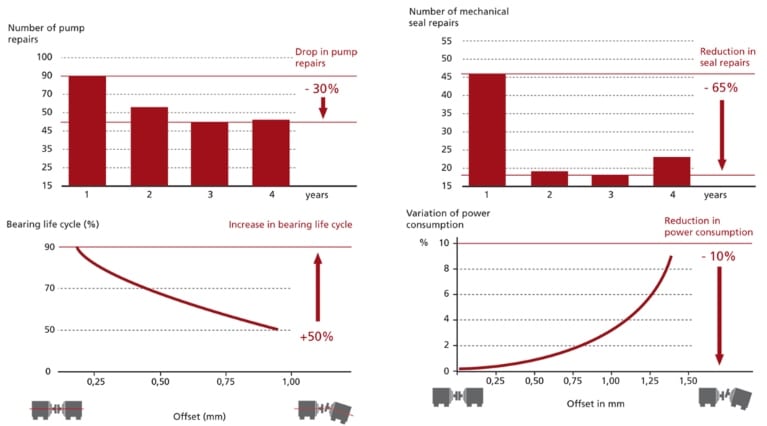
Figure 1. Benefits promised by laser alignment
Example 1: Initial misalignment
Line-over-length can affect the detector measurement range. In other words, the longer the separation distance, the less misalignment can be measured. This complication can arise in many different settings, from overhauling a motor to working with machines with pre-set targets on, for example, wind turbines.
The pitfall: With basic double laser-and-sensor alignment systems, it’s not always possible to measure the initial position of the machine. This predicament forces the user to resort to rough alignment procedures and, therefore, not able to document the “as-found” alignment state.
The advice: Adaptive Alignment systems feature single-laser technology, which helps ease this situation. Gough coaches us to use Freeze Frame in single-laser systems to avoid the laser going outside the measurement range.
“Get the laser in the crosshairs, so that you’re measuring at the coupling, and calculate what’s happening at the feet. This info enables you to know A) the ‘as-found’ state as well as B) how much you have to move the machine,” Gough said.
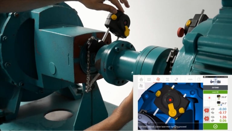
Figure 2. Using Freeze Frame to measure the initial position of a machine.
Example 2: Coupling-Play / Backlash
Backlash or coupling play is a common mechanical phenomenon that occurs when the coupling has high torsional flexibility (is flexible by design) to avoid inadvertent damage to the driven machinery.
The pitfall: Coupling flex or play impacts the alignment measurement, as the change in relative coupling shaft positions change the Y sensor values. During the measurement, as the laser moves or “floats” from left to right, these differences between the heads impact the measurement result, lowering accuracy.
The advice: If your laser alignment tool has Active Situational Intelligence software—another key feature of adaptive systems—use the “Sweep” measurement mode to detect coupling backlash data automatically. Then let the laser alignment tool, with software analytics, remove that data from the calculation.
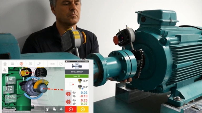
Figure 3: Using data quality enhancement to override the bad data induced by coupling play/backlash
Example 3: Coupled vs. uncoupled shaft alignment
The question here is: Where do you start the alignment? Is it when the machine is coupled or uncoupled?
“If you have a misaligned machine and you try to bolt the coupling together, you’ll have some residual forces and friction to deal with,” Gough says.
The pitfall: If you measure with a coupled-mounted shaft application, you could effectively be measuring a loaded/bent shaft. If you don’t measure the exact unloaded position of the machine, then after you move those values, you won’t correct the misalignment entirely. This situation is particularly challenging to overcome with a double-laser system.
The advice: If you have a shaft alignment application with anti-friction bearings and initial misalignment, remove the tire coupling element, align it uncoupled, and then reconnect the coupling. During the alignment procedure, use the uncoupled PASS mode, another capability in Adaptive Alignment systems. Simply rotate the shafts and let the single laser and sensor head pass across each other, so the measurement points are automatically taken when the heads are in the same relative angular position.
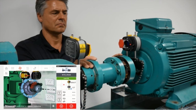
Figure 4: Uncoupled alignment and uncoupled shaft awareness.
Example 4: The movable machine
Back to the line-over-length dilemma. If you need to move a machine during an alignment procedure, which end do you move?
The pitfall: If you move a machine with a laser on, due to line-over-length, you can very quickly slip out of the sensor detector range, forcing you to stop and re-measure before continuing to re-position the machine. Unfortunately, with the double-laser systems, there are always laser and sensor heads on both the moveable and stationary machines.
The advice: Due to the single laser technology, if you move the sensor-side of the machine—not the laser—the problem won’t occur. The line-over-length issue doesn’t take place, and the laser stays well within the sensor detector range while enabling full measurement. Therefore, the single laser should always be mounted onto the shaft of the stationary machine.
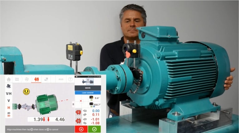
Figure 5: Moving the sensor-end of the machine vs. the laser-end.
Gough asserts that users are well within their rights to expect quick, consistent, and high-precision results from their laser alignment systems. The trick sometimes is to know where the pitfalls lie. For more alignment demonstrations by Gough, watch his other alignment webinar on the Fluke Reliability website.

