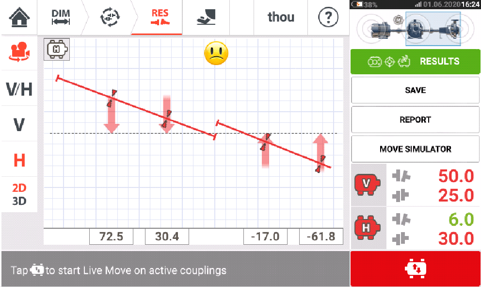
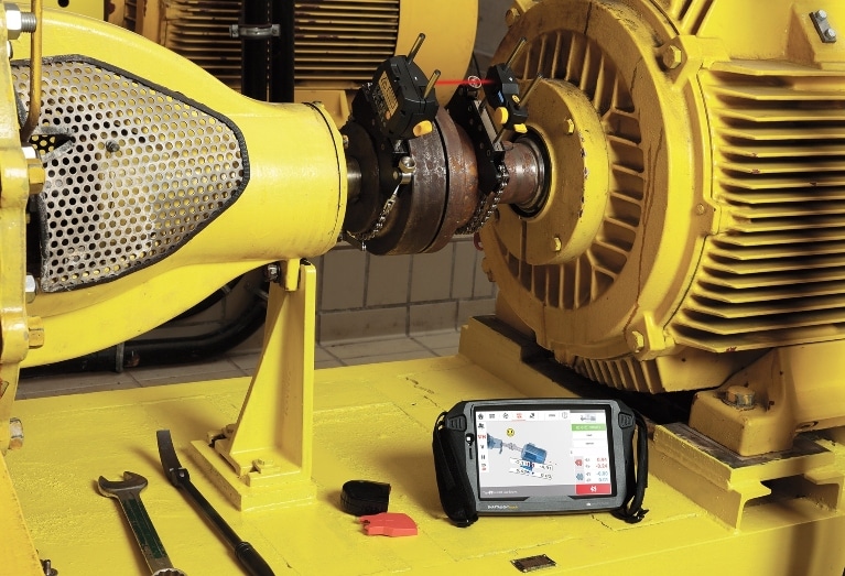
One of the biggest challenges in aligning large or high-speed machines is determining precisely how much the asset must undergo a move to achieve optimal alignment. This determination has long been a manual and tedious process. You calculate the amount and direction of the movement based on the degree of misalignment. Then you move the asset and remeasure, and perhaps move it again, remeasure, and repeat and repeat until you finally achieve alignment.
When you’re dealing with substantial assets that weigh several hundred tons, this process can take considerable time, require numerous resources, and keep the asset out of service for a lengthy period. It can be a hassle – one that is often further complicated by dealing with a machine that is bolt-bound, base-bound, or has limited movement in specific directions. You may delay or even have to reschedule the alignment.
Using adaptive alignment systems with Active Situational Intelligence (ASI) technologies such as Virtual Move Simulator (also known as Move Simulator) can take the frustration and headaches out of this process. You can get not only a precise readout of shaft misalignment but also a preview of the necessary adjustments to align the asset, before actually moving it.
Adaptive alignment systems contain a unique combination of hardware and software that enable users to adapt to virtually any situation in the field, as well as their own experience and skill levels.
How Virtual Move Simulator works
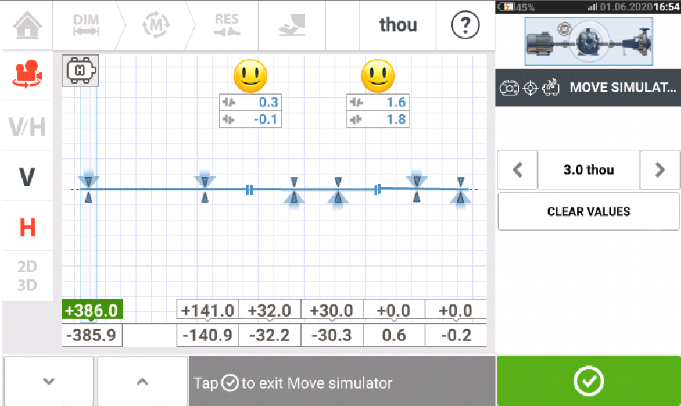
Virtual Move Simulator (VMS), included in the PRUFTECHNIK ROTALIGN touch laser alignment system, simulates horizontal and vertical moves to calculate the precise movement necessary to align shaft couplings. After measuring the alignment of assets, a millwright can enter the estimated amount of change or shimming into VMS and view the results on the screen.
If those virtual moves align the couplings precisely, the screen shows a “smiley” face. If the result is not a smiley face, the technician makes additional adjustments until the smiling face appears. An “OK” is also acceptable in cases where the asset cannot be moved further due to an obstruction.
VMS shows its most significant benefit when used for multi-coupling alignment. Instead of aligning each coupling separately and having to remeasure and adjust each one back and forth, you can simulate the alignment of multiple couplings in one process.
The graphic below shows how this might work in aligning a motor/gearbox/pump setup. You can mount one laser to the left of the coupling between the motor and gearbox and the sensor for that laser to the right of that coupling.
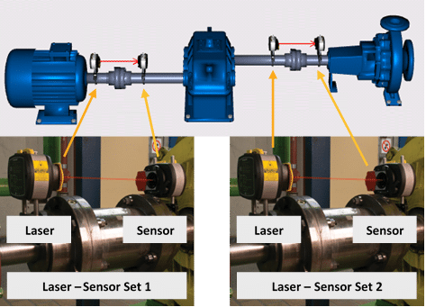
Similarly, you can mount the second laser to the left of the coupling between the gearbox and the pump and the sensor for that laser to the right of that coupling. You can then measure the alignment between the motor and the gearbox and the gearbox and the pump simultaneously as the ROTALIGN touch yields alignment values for the whole machine train (this is known as “Simultaneous Machine Train Alignment”).
After taking the alignment measurement, click on the Virtual Move Simulator button and start the virtual alignment:
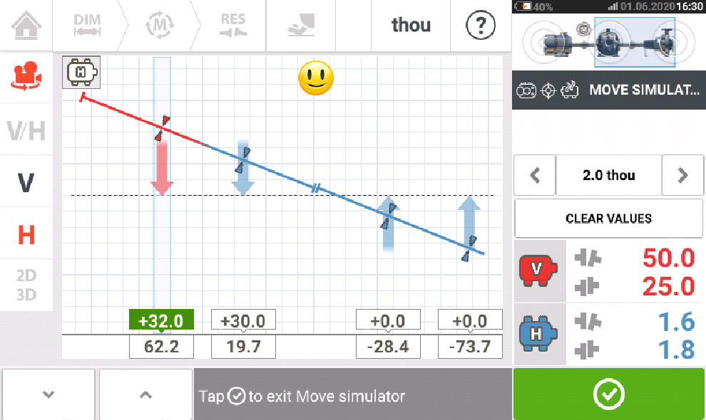
- View the results for the gearbox-to-pump coupling. Make the adjustments necessary to bring those two couplings into virtual alignment by selecting the V (vertical) or H (horizontal) direction and, using the arrow keys, add or subtract movement. Watch the virtual-simulated alignment change in real time.
- Success is confirmed when the smiley face appears on the screen (plus blue correction arrows and colored shaft centerlines).
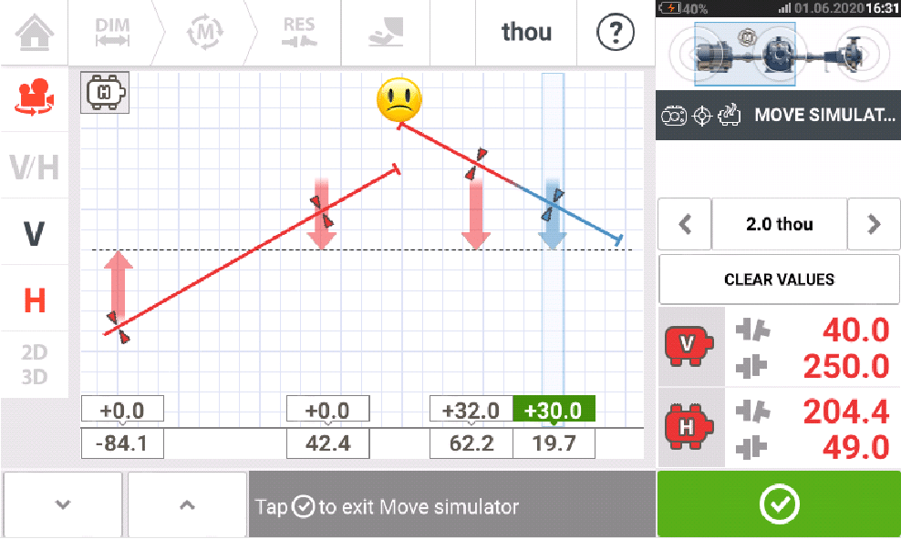
- View the results for the motor-to-gearbox coupling and continue to adjust as necessary, as described in Step 1, to achieve alignment between those two assets.
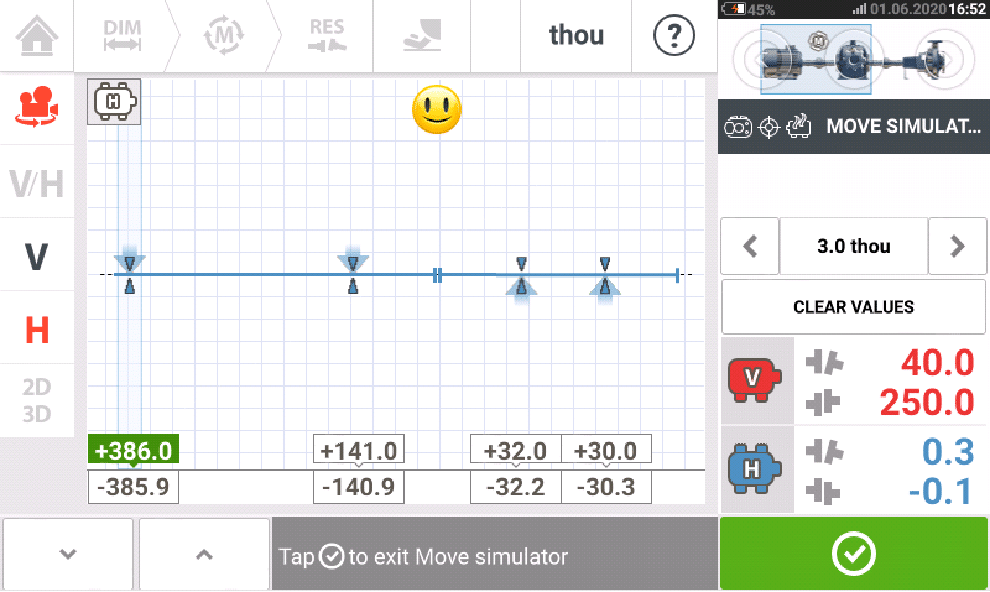
- Simulated alignment between the motor and gearbox is determined complete as indicated by the smiley face shown below.
- When a simulated alignment of each pair of assets is complete, you can see the moves recommended to align all three machine shafts in one virtual-simulated “Live Move.”
With ROTALIGN touch single-laser technology, you can keep the laser and sensors in place and switch from Virtual Move Simulator to Live Move mode. This action enables you to see the values change in real time as the complete machine train is simultaneously physically moved to match the values provided by VMS.
Virtual Move Simulator is just one of many features included in the Active Situational Intelligence software featured in PRUFTECHNIK adaptive alignment systems. This software provides real-time predictive intelligence that is situationally aware to filter out error-causing conditions such as coupling backlash or environmental vibration to increase alignment precision and speed.
Check out how adaptive alignment technologies from PRUFTECHNIK can address your machinery alignment challenges.

