By Spencer Thomas
Correctly installing an extruder screw requires a tightly aligned extruder barrel and gearbox shaft. Follow these instructions to detect and correct misalignment and create a common axis between the barrel and gearbox shaft.
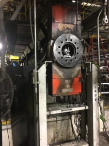
Figure 1 shows a film extruder prepped for initial measurement using the ROTALIGN Ultra, its bore measurement software package and it’s CENTRALIGN Ultra hardware package.
The measurement process assumes that the center of the end of the barrel closest to the gearbox is coincident with the axis of the gearbox shaft. This assumption is justified due to the tight tolerance fit between these two components and the registration geometry that ensures proper mating between these components.
Aligning the gearbox to the barrel requires determining if the center of the end of the barrel furthest from the gearbox is coincident with the axis of the shaft.

Figure 1: Film extruder set up for initial measurement using the ROTALIGN Ultra.
Determining film extruder misalignment
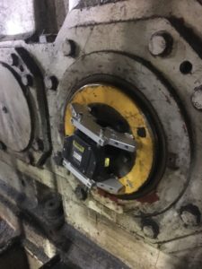
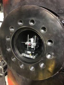
To determine how far the center of the barrel is offset from the gearbox axis, mount a laser to the shaft, as shown in Figure 2. Mount the sensor at the opposite end of the barrel, using the pointer bracket. The bracket allows the user to rotate the sensor while taking radial measurements from the interior surface of the barrel.
To determine the misalignment, rotate both the laser and the sensor into multiple corresponding clock positions. After collecting all of these measurements, the ROTALIGN Ultra determines the vertical and horizontal offset of the end center point of the barrel relative to the shaft’s axis.

Figure 2: Film extruder set up for initial measurement using the ROTALIGN Ultra.
Moving the gearbox to its proper alignment position
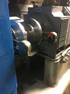
Now the user can move the gearbox to its proper alignment position in reference to the barrel position, as seen in Figure 3. Why move the gearbox instead of the barrel end? Small adjustments to the gearbox account for large offsets at the end of the barrel. Moving the end of the barrel instead of the gearbox risks affecting the barrel’s straightness, requiring a movement of greater magnitude.
Use the Live Move feature on the ROTATLIGN Ultra to monitor gearbox movement. Adjust the alignment in real time and make other accommodations as needed.

Photo 3: Moving the gearbox to its final alignment position.
Aligning the gearbox to the barrel
Moving the gearbox to properly align it to the barrel changes the alignment of the motors to the gearbox. Proceed to align those motors to the new gearbox position.
Use the ROTALIGN to measure the misalignment and shim according to the display to resolve the vertical offset. Millwrights can also use the ‘Live Move’ feature to adjust the horizontal and vertical offsets in real time.
This is a good point to use the ROTALIGN to check for soft foot. If detected, correct the soft foot in accordance with the ROTALIGN measurements. Once all the adjustments are made, take one more set of measurements to verify the machine’s final alignment.

Photo 4: Final measurements and alignment.
Final gearbox and extruder screw installation
At this point, the gearbox should be properly aligned to the barrel, with both master and slave motors aligned such that their shafts are on the same axis. All is ready to install the extruder screw. Having completed the precision alignment, the user can now easily insert the screw into the barrel and couple with the shaft.
See www.pruftechnik.com for more alignment application details.
Spencer Thomas is a Pruftechnik Sales & Project Manager (Advanced Measurements) for Fluke Reliability.
Related articles:
