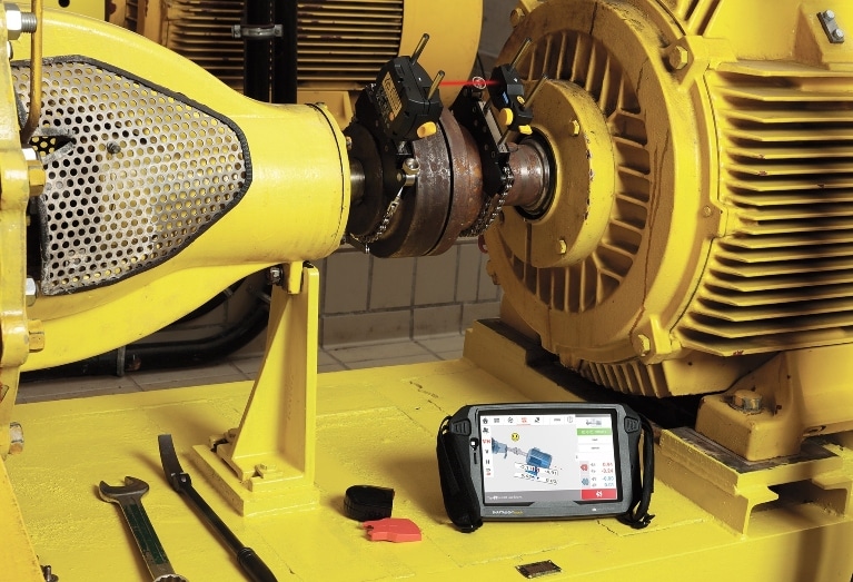
A Spanish company that recycles thermostable plastic needed to verify the alignment condition of a single-screw extruder. The service team planned to use the Prüftechnik CENTRALIGN® laser alignment system to measure the extruder’s alignment condition by measuring the centerline of the barrel and the output shaft of the gearbox that drives the rotating screw.
This Prüftechnik service technicians aimed to ensure that the extruder’s rotating screw would fit into the barrel within tolerances. The screw was supported by a roller thrust bearing located at the gearbox outlet and a ball thrust bearing located just before the feed throat.
Using a static laser setup
The technicians opted for a static laser setup for this application because the centerline had to be calculated as the best fit line and reference points. The laser was installed at the end of the barrel and adjusted with just one movement of the laser housing.
Because the inner face of the barrel is made from a low-magnetic stainless steel, the team used the adapter for non-magnetic bores. It measured five planes: inlet and outlet of the barrel; motor and barrel sides of the gearbox output shaft; and the bearing housing of the roller thrust bearing on the feed throat frame. The setup is shown in Photo 1.
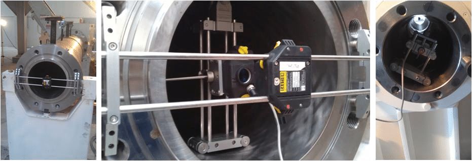
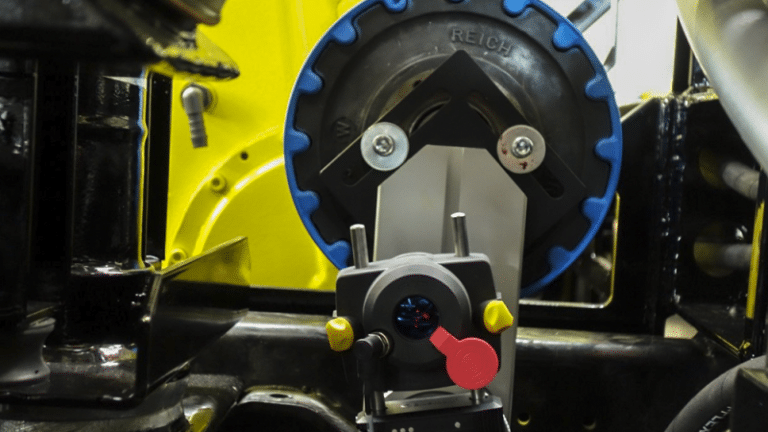
Photo 1: Laser installation. These photos show the laser installation, measured planes and barrel and gearbox measurements. The motor was also aligned with the input gearbox shaft using a smartSCANNER device
Results
The technical team concluded that the single-screw extruder assembly was within the tolerances given by the extruder’s supplier, with best fit centerline and maximum allowed deviation of 0.25 mm, as depicted in Photo 2.
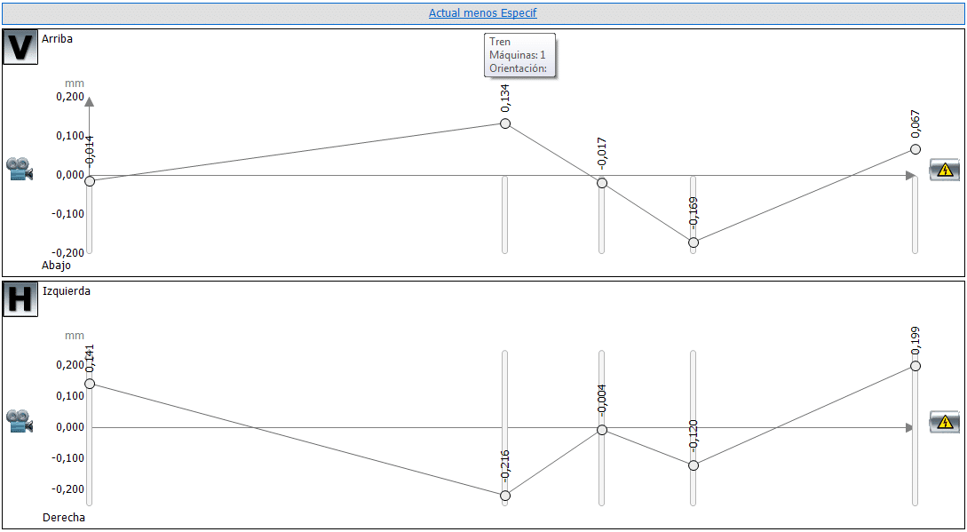
Photo 2: Left to right: barrel output, barrel input, roller thrust bearing housing, barrel side of the gearbox output shaft and motor side of the gearbox output shaft.