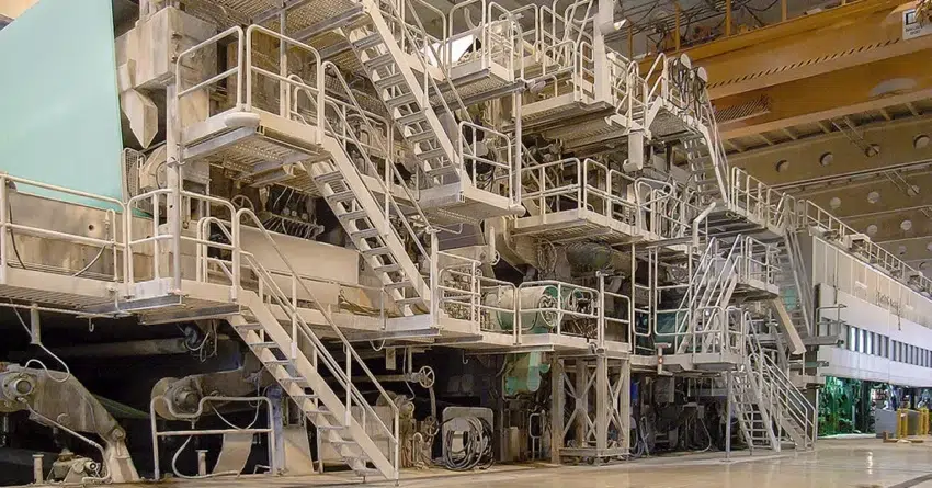
A client in Quebec, the second-largest province in Canada, turned to Fluke Reliability’s ParAlign service to fix the roll machines in its plant after noticing product wrinkling and tracking issues during paper production.
A team of Prüftechnik engineers measured all three press sections in a paper machine while performing this realignment service. In less than 12 hours, the team engineers took their measurements and worked alongside the plant’s mechanics to perform adjustments on the rolls deemed critical to correct.
The result: The client is extremely pleased to have taken this action. But before discussing the findings at the Quebec plant, some background is needed on why maintaining roller alignment in the paper industry is so critical.
Background
Performance is essential to remaining a leader in this highly competitive industry. Producing quality paper requires complex machines with multiple intertwined systems working in harmony. Roller alignment is crucial.
Just as important is roller alignment maintenance, or the ability to align rolls to a reference roll within a specified tolerance. Correctly aligned machine rolls lead to reduced spending on materials and maintenance through decreases in paper breakage, wrinkles, tracking issues, premature bearing wear, and more.
Historically, roller alignment has not been emphasized in the industry as much as other preventive maintenance techniques. However, excessive roll misalignment is directly linked to diminished product quality and unscheduled downtime.
Detecting misalignment during machine operation can be tricky. Given the high demands of run time placed on machines, including the need to run machines 24/7 for weeks at a time, it is useful to know common symptoms visually detected in misaligned machines.
These include:
- difficulties in tracking the product
- telescopic product rolls
- non-homogeneous stretch of felt/wire
- uneven product thickness
- tensions and stress on roller bearings
Many of these signs are too serious to ignore. Improperly maintained machines can lead to component failure, permanent machine damage, and, in the worst case, employee injuries and death.
To date, many paper product manufacturers have themselves used tools and techniques available for solving their roller alignment issues:
- The plumb bob, used for thousands of years, is a simple but primitive way of measuring machine alignment. It cannot offer the precision required today, and there isn’t a digital reading or reporting method for this technique.
- Optical instruments are more advanced but require line of sight to perform measurements. Other factors can distort the accuracy of data gathered using optical devices, including air temperature, humidity, roll accessibility, and a user’s skill levels. Also, the alignment process with optical devices requires significant machine downtime. Even the most advanced devices can require days or even weeks of downtime to complete all necessary measurements.
Prüftechnik, part of Fluke Reliability, has designed and developed an innovative non-optical technique to counteract other roller alignment methods’ limitations.
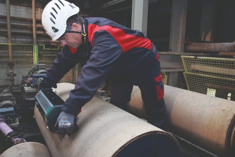
The ParAlign system is a unique, proprietary handheld device that contains three ring-laser gyroscopes, with one gyroscope per axis. Because ring-laser gyroscopes are a military-grade technology, their use is highly restricted. Prüftechnik thus offers ParAlign as a service rather than a device for purchase.
To perform a measurement, the user slides the ParAlign on the roll for a minimum of 20 degrees of the roll’s circumference. The resulting data is instantly transmitted to a laptop via Bluetooth, and a visual readout is displayed. A reference roll is chosen, typically by the client, and the offsets of other rolls are compared to the reference roll. The reference roll can be changed at any point during or after the measurement process.
When the service is complete, the client receives a full report with both initial and final alignment results.
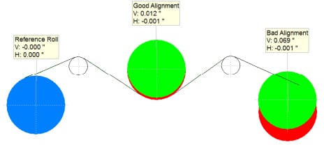
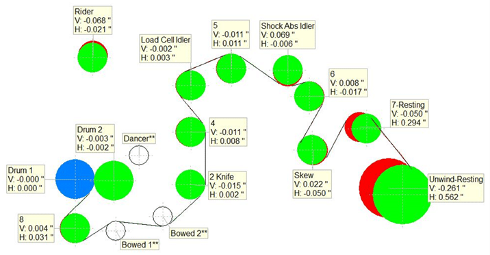
Figure 1.1 is an example of a visual report generated by the ParAlign software. Each roll’s misalignment is represented by a red circle and a green circle. The green circle represents the roll’s operator side, while the red circle represents the machine side. The blue circle in the visual is the active reference roll.
The roll identified as “Good Alignment” in this figure is sitting at 0.001″ in the negative horizontal position relative to the reference roll. Vertically, the machine side is lower than the operator side by 0.012″. To adjust this roll, place a shim underneath the bearing on the machine side.
For this case, we can assume this roll falls within the selected tolerance. The roll labeled “Bad Alignment” is 0.069″ lower on the machine side while also 0.001″ in the negative horizontal position. This roll is assumed to be outside of the targeted tolerance and should be adjusted to improve the machine’s condition.
Correct the alignment of this roll by raising the machine side or lowering the operator side. It is important to analyze each potential alignment correction before performing it to ensure it is not detrimental to a nearby machine structure. If the drive side of the roll mentioned above is coupled to a gearbox and motor, it may be easier to adjust on the roll’s operator side.
Note: Best maintenance practices would include measuring the shaft alignment between these components when any adjustment is made to a connecting component—for example, a roll, gearbox, motor, etc.
Challenges
Back to our Quebec client’s situation. The diagram below illustrates the misalignment found in a press section at the plant.
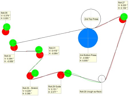
Figure 1.2 shows the initial data of the second press section. Rolls 30 and 29 are labeled as Stretch and Guide rolls, respectively. These rolls are prone to moving during the machine’s normal operation. The alignment of these rolls was deemed not critical by the client.
The rolls with the most wire or product wrap have the most influence on the machine and should be adequately adjusted. The bottom roll was selected as the reference for the press sections because it is fixed and extremely difficult to move. The other rolls typically have more latitude as far as making adjustments.
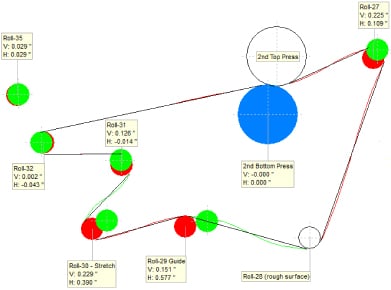
Rolls 35, 32, 31, and 27 were deemed critical by the customer and therefore adjusted. The difference in alignment is quickly apparent. The final image, Figure 1.3, has distinctly less red than the initial image, indicating less misalignment.
Rolls 35 and 32 were easily adjusted. The vertical position of roll 31 presented some challenges. Physical restrictions of the surrounding framework would not allow for easy adjustment during the timeframe of the service.
Roll 27 could not be moved within tolerance because of physical restrictions. The client decided it was not critical to adjust or that further machine alterations could be made later.
Excessive wear to the surface of roll 28 caused permanent damage to the roll face, making it impossible to obtain a measurement. Plans were made to replace the damaged roll once the new roll was in stock.
Results
A few weeks after the project’s completion, the client informed Prüftechnik that its product quality had improved and that the tracking problems had disappeared due to the ParAlign service. They also expressed satisfaction with ParAlign’s speed and service.
Prüftechnik engineers were able to measure and perform adjustments to the multiple press-sections in one day with ParAlign. Using other technologies might have taken several days, and the data would not have been as precise.
In an industry where considerable money is lost if a machine is not operating, ParAlign is the clear choice for roll alignment.

